Principle 3: On-Site Renewable Energy Generation
Renewable energy generation to be icorporated where appropriate. Renewable technologies should be selected holistically, given site conditions and building load profiles.
Design Guide:
Key Design Considerations
Technology Selection
- Select energy generation source to suit the site location. Some of the questions you might consider:
- Could solar energy be a viable solution? This will be dictated by geographical location, micro-climate, orientation, shading, available surface area to building volume, aesthetics.
- Is there a water source (stream, river, lake) nearby that could be utilised?
- Is the site exposed? Is there space to include a wind turbine?
- Decisions on which technology to use and the size of generation system needed will be affected by:
- Planning constraints
- Predicted energy consumption and use profile
- Site conditions
- Building type
- Aesthetics
- Client’s requirements – drivers
- Cost
- For heat: source temperature required, peak temperature required, heating system to be used
- Maintenance requirements
- Available generation area
- If using building integrated photovoltaics (BIPV), roof dimensions may be determined by the size of PV modules.
- If using BIPV, positioning of junction boxes may determine roof design, e.g. if junction boxes are on the underside of modules, a cable void should be formed in the roof build up; if junction boxes on top side of modules, these must be protected from the elements, positioned for e.g. under ridge flashing.
Spacial Considerations
- Ensure sufficient spatial arrangements for connected equipment – charge controllers, inverters, battery storage.
- Size of renewable energy generation system will depend on purpose:
- To meet demand
- To exceed demand (with controlled export) – smart controls and storage needed (and/or electric vehicle integration)
Maximising Benefits
Combining energy generation with energy storage will enable maximum use of generated energy.
Maintenance
- Allow access for maintenance and replacing parts
- Plan for external control of storage systems that are considered for inclusion in aggregation systems and for control of energy. This could include communications protocols such as RS485, MODBUS, or similar, to enable control of charge and discharge of storage systems.
Solar Energy
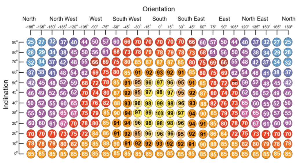
The following diagram, taken from “A Guide to the Installation of Photovoltaic Systems”, is useful to aid design of solar arrays, illustrating the affect of orientation and inclination on PV performance in the UK. This is particularly useful to consult when positioning buildings on a site, as it demonstrates the possibility of generating energy from solar with non-optimum orientations or roof pitches.
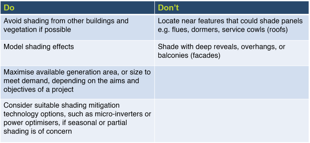
Dos and Don’ts of Solar for Electricity Generation:
Solar PV choice will depend on:
- Planning constraints
- Aesthetics
- PV area to volume ratio
- Main driver
- Available surface area
- Predicted energy consumption
- Site conditions
- Building type
Dos and Don’ts of Solar for Heat Generation:
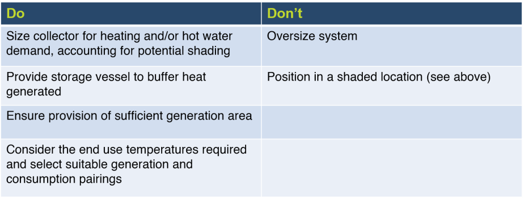
Solar thermal choice will depend on:
- Planning constraints
- Site conditions
- Maintenance requirements
- Predicted energy consumption
- Heating system
- Aesthetics
- Source temperature required
- Building type
- Peak temperature required
- Available surface area
Advice
- Use software packages to aid system design and sizing of proposed PV generation system at early design stage, e.g.:
- Clearly define example usage scenarios and expected logic outputs.
- Use one contractor for renewable energy generation, energy storage and control system installations if possible.
- When designing for building integrated technologies, such as PV, the size of the PV panels, access for maintenance, cable routes, will dictate the roof design
- Local consumption of relatively low power generation could be more effective than long wiring runs to centralised storage systems. Example uses could include using locally generated energy to operate electric blinds to reduce solar gain when power generation is available, or the operation of destratification or air circulation fans when power is available.
- Where available external surface area is constrained, consider the appropriateness of combined systems such as solar thermal and PV combined (PVT).
- If installing small PV arrays, e.g. PV windows, consider how the power generated from that element can be used most effectively.
Resources
- ECA Guide to the Installation of Photovoltaic Systems
- PV Syst
- SPECIFIC
- Sustainabe Energy – Without the Hot Air
- PVGIS Photovoltaic Geographical Information System
- RIBA 2030 Climate Challenge
- Rawlings, R. 2009. Capturing solar energy, CIBSE Knowledge Series: KS15. The Chartered Institute of Building Services Engineers, London, UK.
Technology Showcase:
Photovoltaics
The most commonly used type of photovoltaics (PV) in buildings are silicon, but there are alternatives. Decisions on which type of panels to use will depend on different factors, such as:
- Building type
- Weight
- Cost
- Geometric efficiency – how effectively the available generation area can be utilised for generation – note that although silicon panels are more efficient by area than thin film PV panels, there is often scope for greater coverage with thin film PV, due to the ability to cover entire roof areas, without the need for access routes, for example. Thin film PV is also flexible, so its application is not limited to straight surfaces.
- Aesthetics
- Planning characteristics, e.g. silicon panels may be rejected due to glare in some locations, aesthetics (in Conservation Areas or on Listed Buildings), or due to fears of vandalism – CIGS could be a viable alternative.
This section highlights just some of the alternative ways PV can be used in buildings.
Thin Film – BIPVCo
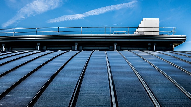
BIPVCo are a company located in South Wales, UK, who manufacture photovoltaic modules using CIGS (Copper, Indium, Gallium and Selenide) solar cells, which they connect to make modules that can be bonded to steel, aluminium or Thermoplastic Polyolefin (TPO) single ply membrane roofing substrates. The modules are flexible, so can be used on curved roof profiles (see Active Office Case Study).
Benefits of the technology include:
- Lightweight
- Works well in low light conditions (ideal for the UK)
- Can be used at any roof angle
- Subtle aesthetics when used with appropriate roofing materials
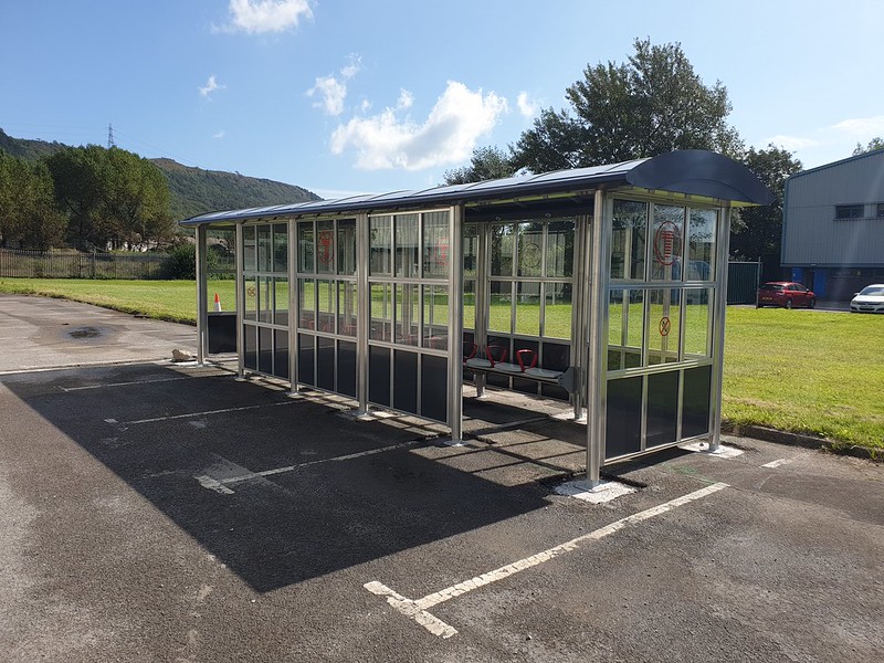
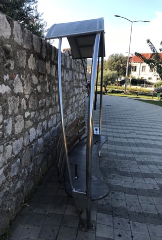
Thin Film – GB-Sol
This is another Welsh company who also manufacture thin-film PV modules. These have recently (2019) been installed on a Transport for Wales prototype shelter, where they will be used to power lighting and display screens within the shelter. These will be particularly relevant for remote rail shelters, which are difficult to get power to.

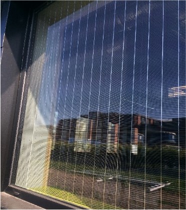
Photovoltaic Windows
NSG Pilkington have developed a PV window called Pilkington Sunplus™ BIPV which consists of narrow strips of silicon wafer embedded into the double-glazed unit, covering 50% of the window pane. The ratio between opaque and transparent area can be adjusted depending on the required power output or shading desired. In individual window applications, this can be classed as micro-generation and the energy generated in this situation is better used locally, to avoid too many losses in power. In the Active Classroom the 77Wp window powers it’s own data logging system and small display screen.
If used in curtain walling applications on larger buildings, it has the potential to generate a significant amount of power, contributing to the overall power supply for the whole building. It could also be used in areas such as conservatories or atriums, in either the roofs or walls, where it could serve a dual purpose in helping to control solar glare and reduce overheating.
Potential future developments for the window include linking the PV power to electronic blinds, where the demand for closing blinds to cut out glare corresponds directly to times of generation. Similarly it could be linked to thermochromic coatings in glazing units, enabling windows to become darker when the sun is strongest.
Emerging Technologies
At SPECIFIC researchers are developing a range of solar cell technologies and processing techniques that will allow high-efficiency thin-film photovoltaics to be manufactured at scale using earth-abundant, low cost materials. They are also working to understand the stability and lifetime of these devices, by characterising their degradation mechanisms and finding ways to improve longevity.
The researchers work with the most promising photovoltaic technologies to find ways to manufacture them at scale. Currently these include three distinct technologies: perovskites, CZTS (copper, zinc, tin, sulphur) and organic photovoltaics.
Perovskite Solar Cells (PSCs) are a relative newcomer to the photovoltaic industry but, with efficiency now reaching similar to that of the current market leader, silicon PV, researchers are focused on upscaling PSCs.
Contrary to silicon PV, which requires high temperature and high vacuum depositions, PSCs can be solution-processed at a low temperature, significantly reducing their manufacturing cost and embodied carbon (Crystalline silicon PV is processed at 1800⁰C. Low temperature processing enables use of plastic substrates to make flexible solar cells, while the ability to solution process allows use of well-developed printing and coating techniques, such as: Screen printing; Inkjet printing; Gravure printing; Slot-die coating; and Spray coating.
These advantages combined enable use of roll-to-roll manufacturing.
Oxford PV, who the team at SPECIFIC work closely with, are currently working on commercialising this technology.
Photovoltaic Thermal Hybrid Solar Collectors
It is possible to combine both PV generation (for electricity) with a solar thermal collector (for heat) in one system. On a PVT panel system, excess heat generated is transferred via a heat exchanger on the back of the PV panel and into a heat transfer liquid that is supplied to the heating system. This improves the efficiency of the PV element, as it cools them down. These are particularly useful for space-constrained areas, as the two functions of generating heat and electricity are combined into one panel. While research into this technology has been underway for many years, PVT systems are not currently (2020) widely used in buildings. Examples include:
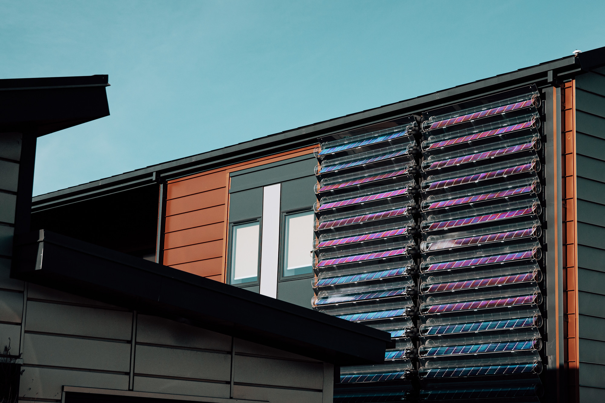
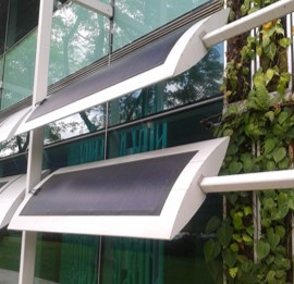
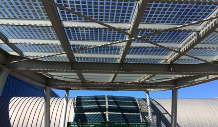
Virtu by Naked Energy
Evacuated tubes contain PV plates to enable capture of both solar thermal (T) and solar photovoltaic (PV) energy in a combined PVT system. A solar absorber behind the PV plate cools the PV plate by drawing heat away from the plates and transferring into a thermal store. This maintains the efficiency of the PV plates, while providing valuable heat energy for the building. The evacuated tubes reduce thermal losses. These can be installed on roofs or facades. An example of the first façade installation of this system is shown in figure 4.5 below.
PowerCollector by Solarus
This C-PVT system consists of a concentrating, hybrid solar photovoltaic (PV) and solar thermal (T) panel. A curved mirror concentrates the solar energy and allows the system to collect and reflect maximum sunlight throughout the day. Water is used to draw heat away from the solar PV cells, which improves electrical performance and extends cell longevity. While cooling the cells, it transfers the heat into a heat exchanger for space heating and hot water.
Other renewable technologies for heat generation:
- Geothermal with Ground Source Heat Pumps (GSHPs)
- Water-source thermal
- Clean Combined Heat and Power (CHP) systems
- District heating from low carbon source
- Biomass from waste products
- Biogas
- Mine water (specific sites)
- Grey water heat recovery
- Fuel cells if using renewables
- Waste heat recovery solutions
Electricity Generating Landscape Features


Other renewable technologies for electrical generation:
- Wind power – dependent on location and specific site conditions
- Freshwater turbines – dependent on specific site conditions
- Combined heat and power (CHP) if low-carbon source, such as bio-methane fuel used
- Tidal power – dependent on location. Would need energy storage
- Hydrogen, if generated using low-carbon energy source
Heat Generation
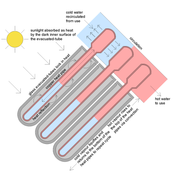
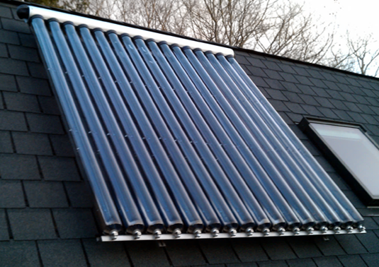
Evacuated Tubes
The most popular and efficient type of solar thermal collectors are evacuated tube collectors which comprise rows of insulated glass tubes with copper pipes at their core, which transfer heat to a water tank. An inner glass tube is suspended inside a larger outer tube, which are fused together at one end. The air is pumped out of the space between the small inner tube and the larger outer tube creating a vacuum thermal insulation layer, which is key to reducing the heat loss from the collector. The inside of the inner glass tube is coated with a selective light absorber such as aluminium nitrate or titanium nitrate oxide, which helps maximise the absorption of solar radiation over a large range of wavelengths. An absorber plate, normally made of copper, then runs the length of the inner glass tube, which absorbs the heat and transfers it to a heat transfer fluid. In passive systems, convection drives the movement of the heating fluid in each solar collector tube and when the transfer liquid is heated it evaporates and turns into a vapour. This rises to the top of the collector where the heat is transferred via a heat exchanger to another liquid – usually water, that is then stored in a hot water storage tank. The transfer liquid then condenses and falls back down the evacuated tube ready for the next cycle.
Evacuated tubes have a conversion efficiency of over 70%, enabling them to produce enough heat to provide hot water to use in heating systems. This is achieved by their construction, i.e. with an insulation layer, and as they are virtually unaffected by air temperatures. The cylindrical shape of the evacuated tubes enables them to collect sunlight throughout the day and at all times of the year.
Benefits:
- Relatively easy to install as they are light, compact and can be carried onto a roof individually.
- If one tube fails, it can be replaced without the need to replace the whole collector.
- The vacuum inside the tubes can last for over twenty years, providing an efficient and durable system which prevents the reflective coating inside the tube from degrading.
Flat plate collectors
Another common type of solar thermal collectors are flat plate collectors, which consist of a dark coloured flat plate absorber (usually copper or aluminium) with an insulated cover, a heat transferring liquid containing antifreeze (such as glycol) to transfer heat from the absorber to the water tank, and an insulating backing. The flat plate increases the surface area for heat absorption and is capable of generating 50 litres/m2. A well-designed commercial solar thermal system may be able to satisfy around 30 to 40% of the annual hot water load, known as the solar fraction (SF)” (and 100% during the summer) (source). The heat transfer liquid is circulated through copper or silicon tubes contained within the flat surface plate.
An alternative to metal is to use a polymer flat plate collector, which are less prone to freezing, so can use water as the heat transferring liquid instead of antifreeze. This enables them to be plumbed directly into a water tank removing the need for a heat exchanger, hence increasing their efficiency.
Flat plate collectors are generally less compact and less efficient than evacuated tube collectors, so are less expensive, and have a life expectancy of over twenty-five years.
Thermoslate
THERMOSLATE® is natural slate roofing that makes use of the properties of natural slate to convert sunlight into energy to produce heating, hot water, or pool heating. This solar thermal collector system adapts to all types of construction requirements and is imperceptible once installed.
Emerging Technology: Evacuated flat plate collectors
A high-vacuum flat plate collector can rival evacuated tube collectors in terms of efficiency, reaching peak yields by avoiding convection losses inside the solar collector, through use of a high vacuum thermal insulation. Combining the insulation properties of the vacuum with a large surface area offers excellent visual and thermal characteristics, and means they are much thinner than conventional collectors (source). They can also utilise diffuse irradiation.
Transpired Solar Collectors (TSCs)
Most industrial and commercial buildings require large quantities of ventilation air to maintain a healthy work environment. In some months of the year this needs to be heated to provide a comfortable work environment. TSCs provide pre-heated fresh air to a space, as well as lower fuel bills and improved indoor air quality. Maintenance costs are low as it is so simple and it has a 30-year life span. While this is a good choice for large volume spaces, such as industrial buildings and sports halls, it has also been used on smaller buildings, such as the Active Classroom and Active Homes Neath, where it provides a pre-heat to the ASHPs used for space heating and DHW, discreetly fitting into the cladding panels.
How they work: The pre-finished steel has enhanced thermal absorption properties and absorbs the sun’s radiant energy, subsequently heating the boundary layer of air to the exposed side of the metal skin. Negative air pressure created within the cavity by a ventilation fan draws ambient outside air, warmed from the surface of the steel, through the micro perforations in the transpired solar collector’s surface. Fresh heated air from the cavity is then fed either directly into the building as ventilation air (industrial applications) or ducted into a HVAC unit (commercial & residential applications), where it is used as a pre-heater to the main heating system.
Performance of a TSC is affected by factors such as :
- Size of collector
- Cladding profile
- Colour of cladding
- Shading
- Exposure to wind
- Location in relation to connected services
- Elevation orientation
Case Study: The Solar Heat Energy Demonstrator (The SHED)
A solar air collector and a solar store are being demonstrated on an industrial unit in Margam which was constructed in 1990 and has a poor-quality building envelope. Two collectors, each approximately 250m2 have been installed on the southwest facing wall of the building. One collector is used to heat the space directly via a simple fan unit, while heat gained from the second collector is stored in a large water tank to be used the following day. This is the first prototype of the solar storage system and has been operating since 2011.
The building was formerly heated via a gas fired boiler, but since this system was installed, the gas boiler has been decommissioned and no gas has been used for five years. The building is heated purely from the solar air system.
Heat from the collector is passed through a heat exchanger and into a heat pump to raise the temperature before delivering it to the thermal store. Heat is then dissipated through fan coil units as and when it is required. This operating strategy provides 100% of the heat demand of the building with no gas consumption: 40% direct heat from TSC and 60% heat from the solar store.
This equates to a 44% saving on the operating cost of the previous gas-fired system, and a CO2 saving of 48% on emissions, demonstrating a viable renewable heating system.
Photovoltaic Thermal Hybrid Solar Collectors
It is possible to combine both PV generation (for electricity) with a solar thermal collector (for heat) in one system. On a PVT panel system, excess heat generated is transferred via a heat exchanger on the back of the PV panel and into a heat transfer liquid that is supplied to the heating system. This improves the efficiency of the PV element, as it cools them down. These are particularly useful for space-constrained areas, as the two functions of generating heat and electricity are combined into one panel. While research into this technology has been underway for many years, PVT systems are not currently (2020) widely used in buildings. Examples include:
Virtu by Naked Energy
Evacuated tubes contain PV plates to enable capture of both solar thermal (T) and solar photovoltaic (PV) energy in a combined PVT system. A solar absorber behind the PV plate cools the PV plate by drawing heat away from the plates and transferring into a thermal store. This maintains the efficiency of the PV plates, while providing valuable heat energy for the building. The evacuated tubes reduce thermal losses. These can be installed on roofs or facades. An example of the first façade installation of this system is shown in figure 4.5 below.
PowerCollector™ by Solarus
This C-PVT system consists of a concentrating, hybrid solar photovoltaic (PV) and solar thermal (T) panel. A curved mirror concentrates the solar energy and allows the system to collect and reflect maximum sunlight throughout the day. Water is used to draw heat away from the solar PV cells, which improves electrical performance and extends cell longevity. While cooling the cells, it transfers the heat into a heat exchanger for space heating and hot water.
Other renewable technologies for heat generation:
- Geothermal with Ground Source Heat Pumps (GSHPs)
- Water-source thermal
- Clean Combined Heat and Power (CHP) systems
- District heating from low carbon source
- Biomass from waste products
- Biogas
- Mine water (specific sites)
- Grey water heat recovery
- Fuel cells if using renewables
- Waste heat recovery solutions